
Tractor: First Look
Tractor is a framework for driving automated testing. The first focus is on amplifier testing using both the QA401 Audio Analyzer and the QA450 Programmable Load. These 3 applications work together to make it easy to quickly script a series of automated measurements--without writing any code--in a production or development setting. If you are able to write code, the Tractor framework should enable you to write handlers for other test equipment. For example, you might want to test an amplifier at several different voltages and so you'd write the code to support a programmable power supply.
The source code for Tractor will be changing a lot as the project evolves. But if you are curious to have a look at where things are now, the source is located here on Github. Just fork and build.
Software Architecture in a nutshell
There is a class called TestManager in Com.QuantAsylum.Tractor.TestManagers . This is an abstract class that implements the functions it expects the hardware platform can handle. For example, there's a function to set the audio generator to a specific level and frequency. And there's a function to query the current consumption of the DC supply that is powering the amp. This is an abstract class, meaning you would derive a version from this class based on the hardware configuration of your test setup. And be forewarned, the names in here will change a lot as things get cleaned up.
In this first release, a derived class called QATestManager.cs is provided in that directory. This inherits from the abstract class TestManager and implements the required virtual functions. In this release of Tractor, this is the sole profile supported: You must have both a QA401 and QA450 to use Tractor. But in the future, there can be a QA401-only class, or a class that uses a GPIB power supply. Or whatever you might desire.
What can Tractor do?
Two apps are shown below. On the left is Tractor and on the right is the UI for the QA450 programmable load. From a control perspective, the QA450 UI is fairly simple. You can turn turn the power supply to the amp on and off, see the current consumption of the DUT (the amp you are testing), control the loads, and see the temperature of the load resistors.
Under the covers, the QA450 application implements a REST interface. This is a change in direction for us as to date QuantAsylum tools have implemented DotNet Remoting. However, this was deprecated by Microsoft several years ago as REST and other app-to-app interfaces based on HTTP became more popular. The benefit of REST is that anything that understands how to browse the web can use REST. The downside of REST, versus DotNet Remoting, is that it takes a fair bit more effort to send more complex types over the wire. But a host of solutions have emerged to make that easier.
If the QA450 app is running on your desktop, and you go to the link http://localhost:9450, then you will see a description of the implemented interfaces over HTTP. And chances are high your favorites language supports REST.
Querying the current load setting on the QA450 is as easy as calling http://localhost:9450/impedance. And setting the current load on the QA450 is as easy as doing an HTTP PUT.
Inside the file QA450.cs, you'll see a simple client-side REST implementation for the QA450.
Moving on, you see the Tractor application on the left.

Let's start by adding a test. To do that, we click the "Add Test" button, and the following dialog appears:

This dialog allows us to pick a test, and give the test a name. We'll start the test by asking the user to enter a barcoded serial number on the DUT. This will be entered with a Bluetooth scanner.
After clicking OK, the main UI changes as we see below. We have started to build a test plan! The test details are shown in the right panel. Some of these might make no sense given current context (such as right/left channel). As the code is refined, these things will be polished up. But for now, they can be ignored.

OK, so we have a test that asks the operator for a serial number via Bluetooth barcode scanner. Next, let's add a test that turns on the DUT. This is controlled by the QA450. There is a test called Power01 that will turn the supply to the DUT on or off and also measure the current of the amp. Since the amp has just turned on, this measurement will be the quiescent current of the amp with no signal input. We don't know much about the amp yet, so let's pick a large allowable range for the quiescent current. Below, you can see we've considered 100 to 200 mA to be considered passing based on the TPA3255 spec. Any current measured outside this range will be considered a failure. Later, after we've measured perhaps 100 of these amplifiers during a proto run, we can look at a histogram of the quiescent current and adjust the limits based on engineering evaluation.

Thus far, we've asked the user to scan a barcode for the serial number, and we've turned on the power to the amplifier and checked if it's within a reasonable range. So far so good.
Next, lets add another test to test the amplifier gain at a given load impedance. Here, we open the Add Test dialog again, and ask to see all the tests that are related to Gain and Levels. There are two gain tests that show up, Gain01 and Gain02. Reading the test description, we see that Gain01 doesn't care about the load impedance, and Gain02 does. Since we want to test the amplifier with a load, we pick the Gain02 test.

Now the UI gets a litte more interesting. And there are a lot of details we can change. Below, the defaults are shown.

Below, we'll go over each of the fields. Remember, our goal is to the test the amp at 1 KHz with a 8 ohm load. But more specifically, we want to make sure the amp gain is around 27.5 dB which is the design target.
The fields to setup are as follows:
Freq: We want to test at 1 KHz. If we also wanted to also test at, say, 20 KHz, we 'd just add another 'Gain02' test with 20 KHz specified.
Output Level: This is the level (dBV) we want from the QA401 generator going into the amp. For now, we'll pick -10 dBV. With a gain of 27.5 dB, this means the amp will output 17.5 dBV = 7.5 Vrms. With our 8 ohm load, this will be about 7W. We could go much higher or much lower. If the QA401 output were set to 5 dBV, then the amp output would be 32.5 dBV = 42.4Vrms, or 222 watts into 8 ohms.
ExtGain: This field is where we specify any external gains we might have in the lineup outside of the amp gain. The QA450 has a fixed gain of -6 dB. So we enter that here.
The Minimum Pass Gain is the minimum gain we'll accept to consider the test "passing." Since the design is 27.5 dB, let's pick a gain of 27 to be passing.
The Maximum Pass Gain is the maximum gain we'll accept. We'll pick 28 dB. Combined with the Minimum Pass Gain, this means this amp must deliver a gain of 27.0 to 28.0 in order for it to pass this test.
Output Impedance is 8 ohms. We could also pick 4 ohms here, as the QA450 can provide both 4 and 8 ohms. T
Input Range is the attenuator setting we want on the QA401. On the QA401, there are two options here: 6 dBV range or 26 dBV range. Since we expect the amp output will be 17.5 dBV, we want the 26 dBV range.
Let's rename the test name to be "Gain02-1 KHz @ 8 Ohms" so we can better understand it in summary reports.
Retry Count is the number of times we'll retry the test in case of failure. Default is 2. A test can sometimes fail even though the DUT is operating correctly. This might be due to a timing issue related to the interaction between the test equipment. These timing issues sometimes arise because the settling time is often intentionally limited to minimize test time. But if a failure is measured, then a second test will be run automatically.
Finally, we specify we want the test performed on both the right and left channels. Normally, it's "free" to test both left and right channels and they are acquired as a pair. But there are times where you might not want a failure on the right channel to be considered. For example, if you are testing a mono amp.
With the above changes made, our Test Details appears as follows:

Now, let's hit the "Run Tests" button and see what happens:

From the above, we see the serial number for this test board (entered via barcode scanner), we can see the 110 mA quiescent current, and we can see the gain is 27.43 dB on both the left and right channels. And we see that took 6 seconds. Hopefully a reasonable start!
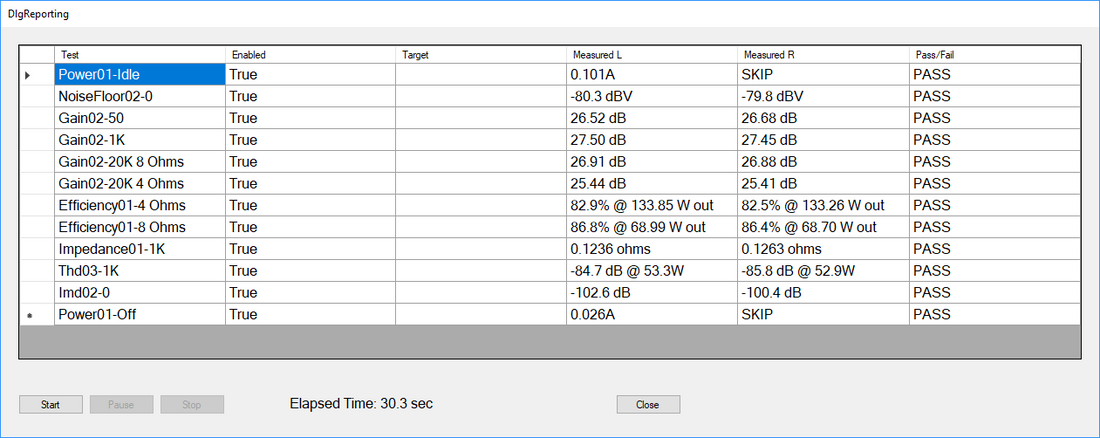
A more interesting test profile appears below for a TI TPA3255 2x300W stereo Class D amp. This includes measurements at several points of interest, including:
Gain at 50, 1KHz and 20 KHz into 8 ohms, with the 20 KHz measuring gain at both 4 and 8 ohm loads. In a class D amp, this is important as the load impedance has a large impact on the response at 20 KHz.
Efficiency is also measured. Efficiency is a key benefit for class D amps and also a quick measurement that captures the health of the build on a particular unit.
Impedance is also an easy measurement to make that can provide detailed insight that the build was done correctly. The impedance is computed by measuring the output level at 8 and 4 ohms and solving for the unkown impedance.
Finally, THD at 1 KHz and IMD at 19/20 KHz are also checked at higher power levels. The full test run is shown below:

We can run the test again on the same hardware and compare the results between the two runs. In the plot below, Run 2 is the test run from above, and Run 1 is another run. Side by side you can see the repeatability is quite good. The current sensor on the QA450, which is used to sense DUT current, is a hall sensor rated for 15A, and the resolution is around +/- 20mA or so, which leads to the variability you see on Efficiency and Quiescent current tests.

Test Reporting and Logging
Tractor currently generates two logs. The first is an HTML log file. This makes it easy to chronologically review the tests performed at a test station. For most tests, you can also click on a link and see the exact image the audio analyzer captured to determine the pass fail. So, if you see a failure for THD, you can see the spectrum and spur that caused that failure. The HTML file excerpt for the test run above is shown below, along with links to the spectrum images.

In addition to the HTML log, each measurement will be logged to a database. You will need to provide a connection string to that database you are running, but once that is done all measurement data will be logged. That will allow more conventional reporting tools to generate histograms on various metrics. For example, you can query "What was the gain at 1 KHz of all units built in March of 2018." Tractor will allow you to quickly look at histograms and yield data, but we don't expect it will become a full fledged yield analysis tool.
Summary
Above, we constructed an automated 30 second test that would take perhaps an hour or two to put together and tweak, without writing any code.The integration between the QA401 Audio Analyzer, the QA450 Programmable Load, and the Tractor software allows this quick and easy test assembly.
Tractor is evolving but hopefully this quick look makes it clear where automated testing based on the QA401 and QA450 is be headed.
Like what you just read? Join our mailing list at the bottom of the page.